Blog 1: Gears

HIII EVERYONE! Welcome back to season 2 of my blogging series where I will be sharing my experiences in Chemical Product Design and Development (CPDD).
Today's blog will be about gears!! This blog will mainly discuss understanding gears, their mechanisms, and finally, my reflections and experiences using gears!

THIS BLOG MAY BE VERY BORING AT FIRST BUT PLEASE KEEP READING TILL THE END!!
Section 1.0 : Definition & Relationship of M, PCD & Z

Picture 1: Labelled gear diagram
Gear Module (M) refers to the size of the gear teeth on each gear.
Pitch Circle Diameter (PCD) is the diameter running through the centre of all the gear teeth.
Number of teeth (Z) refers to the amount of gear teeth that each gear has.

Picture 2: Relationship between M, PCD & Z
Relationships:
As PCD increases, M will increase because PCD is directly proportional to M.
As Z increases, M will decrease because Z is inversely proportional to M.
EXTRA INFO ON GEARS WORKING TOGETHER!!!!

Picture 3: Relationship between M,PCD & Z using Gear Trains
Idea of Gear Trains:
Consists of 2 or more gears that have the same module.
Gears in contact must have the same module to ensure tight fitting to ensure they turn smoothly.
The equations of each gear can be equated to each other through the module and be rearranged to form new equations as seen in the picture below.
Section 2.0: Gear Ratio
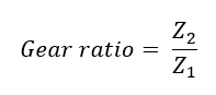
Picture 4: Gear ratio equation
Z with a subscript of 2, refers to the number of teeth on the driven gear while Z with a subscript of 1, refers to the number of teeth of the driving gear.
A gear ratio which is also commonly referred to as speed ratio is used to draw a relationship between the number of teeth on two gears that are touching each other.
Section 2.1: Relationships between gear ratio & rotational speed

Picture 5: Gear ratio relationship to torque
T with a subscript of 2, refers to the torque of the driven gear while T with a subscript of 1, refers to the torque of the driving gear.
From the equation above, it can be seen that the output speed relationship is inversely proportional to the gear ratio.
As the number of teeth of the driven gear increases, the gear ratio increases, and the output speed decreases. Hence, the driver gear will rotate slower while the driven gear will rotate faster.
Section 2.2: Relationship between gear ratio & torque

Picture 6: Gear ratio relationship with rotations per minute
RPM with a subscript of 1, refers to rotations per minute of the driving gear while RPM with a subscript of 2, refers to the rotations per minute of the driven gear.
From the equation above, it can be seen that the torque (T) relationship is directly proportional to the gear ratio.
As the number of teeth of the driven gear increases, the gear ratio increases, and the torque increases. Hence, the driven gear can be used to lift heavier objects with lesser effort.
Section 2.3: Overall relationship between the number of teeth, rotational speed & torque using Gear Ratio

Picture 7: Overall relationship between number of teeth, RPM & Torque
From the equation, we can conclude that there is a direct link between the number of teeth on a gear, torque and rotational speed.
As the number of teeth increases, torque increases, however, rotational speed decreases. This will result in the driven gear having a lower rotational speed but a higher torque that will allow it to move heavier objects with ease using lower input force.
On the other hand, as the number of teeth decreases, torque decreases, however, rotational speed increases. This will result in the driven gear rotating faster but more input force will be needed if it is used to move heavy objects.
Section 3.0: Designing a better hand-squeezed fan
Problem statements:
It was very difficult to crank the handle to make the fan turn.
A high input force is needed to crank the handle.
Original Design

Picture 8: Layout of the gears of the original hand-squeezed fan
Explanation of new design with pictures

Picture 9: Picture of how the new handle mechanism works
The new design involves the use of a crank that has a spring that pulls it back into its original position after being pressed.
The handle also has gear teeth to contact the smaller gear on the first compound gear. This increases the gear ratio or speed ratio to turn the first compound gear and the subsequent gears including the fan will turn faster.

Picture 10: Gear layout of the modified hand-squeezed fan
The first idler gear should be made into a compound gear to reduce the amount of input force needed when the handle is cranked. Through the use of compound gears, the final gear ratio may also increase as the larger gear on the handle meshes with the smaller gear of the first compound gear. Additionally, the larger gears of the subsequent gears will also mesh with the smaller gears on the compound gear. Hence, causing the fan to move at higher speeds as output speed increases and speed ratio increases.

Picture 11: Picture of gear internal before and after the handle is pressed
The second compound gear is held by a slope using a pin on the fan shell. When the handle is cranked, the first compound gear will connect to the smaller gear on the second compound gear, causing it to turn and move up to the slope. This will cause the first compound gear to connect to the second compound gear. Hence, this will cause the second compound gear to start turning, causing the driven gear to turn and the fan to start spinning.

Picture 12: Picture of the fan external before and after the handle is pressed
When there is no input force on the crank handle, the handle, the first compound gear and the second compound gear will return to their original position which causes the gears to turn in the opposite direction from the time the handle was cranked.
The disconnection of the moving first idler gear from the second idler gear will cause the fan blade connected to the driving gear to continue turning in one direction instead of changing the fan direction. Hence, this will not only ensure that the fan functions effectively and efficiently but it will prevent the backlash from the force of 2 gears moving in the same direction and clashing against each other which will damage the gear teeth, resulting in wear and tear.
Section 4.0: Water Bottle Challenge
Calculation of the gear ratio:

Gear layout:

Picture 13: Gear layout in-real-life

Picture 14: Drawn gear layout
Calculating the number of rotations to crank the bottle up:

Video of gears turning to lift the bottle:
AND THAT'S IT FOR OUR WATER BOTTLE CHALLENGE!
Section 5.0: Reflection
ENOUGH OF THE TECHNICAL STUFF!! TIME FOR THE MORE INTERESTING PART!! (I hope)

In my opinion, this practical was very detailed and useful as it put our understanding of gears to the test by making us experience the use of gears to complete a task. In our case, the task was to lift a water bottle using a set of gears with the highest gear ratio. Through this experience, my group and I did many trials and errors making the practical very stressful and frustrating. However, we still managed to obtain the desired gear ratio used to help us reduce the amount of force needed to lift the water bottle.

After achieving the desired gear ratio to lift the water bottle, my group and I continued to experiment with different combinations as we wanted to find ways to improve the gear ratio and increase the torque of the driven gear. However, using the limited time left that we had, we were still unable to find a higher gear ratio. Hence, we settled with the gear ratio of 26.67 along with its gear arrangement. This has also made me realise that there is never necessarily a right or wrong answer because different gear arrangements can still achieve the same gear ratio. Hence, this practical had changed my perspective on having fixed answers and solutions for every problem.

This practical has also made me see gears in a new light. Before the practical, I always thought that gears were just used as basic tools used in olden days such as for pulleys and bicycles. However, this practical made me realise gears are still commonly used every day such as the use of gears in vehicle steering. Hence, I believe that the design of gears is one of the most beautiful and amazing mechanisms mankind has made and has used to evolve through the centuries due to its potential.

In conclusion, this practical has taught me to appreciate gears more as they are not only just a tool used for vehicles and moving parts, but they are also works of art that hold lots of potential. They are truly very interesting which made our learning in this practical even more unique. This practical has also allowed my group and I to put our critical thinking and problem-solving skills to the test and refine them further with the help of learning about gears. Hence, I believe this experience will help us become more accustomed to using our critical thinking and problem-solving skills to help achieve our desired results and give us a broader engineering experience for the future.
FINALLY FINISHED WITH THE REFLECTION!!!!!!!!! RAAAAAHHHHHHHHHH!!!!!!!!!!

That's all for my first blog! It has truly been a long time since I had to write a blog, especially one that is this long. However, I hope that my blog has been informative and helpful to everyone reading this!
THANK YOU FOR READING!!
Stay tuned for the next episode of my blogging series!


Comments