Blog 2: Arduino Programming

Updated: Feb 1, 2025
HIII AGAIN!!
Welcome to the second episode of my blogging series!
In today's blog, we will be learning more about programming using Arduino and how each code works hand in hand to perform each task!!
Mainly, this blog will talk about how each program works to complete its respective tasks and I will be reflecting on my experience in programming. There will also be a little bit of extra content that I would like to share at the end of this blog!!
SOOOOOO
KEEP READING!!!
HEADS UP!!
Before diving into the main part of my blog, here is some context!
For this blog, we were given 3 tasks and had to choose only 2 out of the 3 to program and explain.
The 2 tasks are,
Interface an LDR to the Maker UNO board and measure its signal in the serial monitor of Arduino IDE and,
Interface 3 LEDs (Red, Yellow, green) to the Maker UNO board and program it to perform an action (Fade or Flash, etc). Use the pushbutton on the Maker UNO board to start/stop the action.
LETS DIVE IN NOW!
Task 1: Using a Light Dependent Resistor (LDR)
Program used:
int analogVal;
const int ldrPin = A4;
const int ledPin = 5;

void setup()
{
  Serial.begin(9600);
}

void loop()
{
  analogVal = analogRead(ldrPin);
  if (analogVal < 100) {
    digitalWrite (5, HIGH);
    delay(1000);
  }
  else {
    digitalWrite(5, LOW);
  }
  Serial.println(analogVal);
  delay(1000);
}
Explanation of code above:
int analogVal;
const int ldrPin = A4;
const int led = 5;
The first sentence, declares an integer variable called "analogVal" used to store analog readings.
The second sentence, establishes a constant integer variable called "ldrPin" which is use connect the LDR to the analog PIN A4.
The third sentence, establishes a constant integer variable called "led" to PIN 5 which is connected to the LED bulb and is also used to control it.
Serial.begin(9600);This sentence under "void setup()", is used to establish serial communication between the Arduino board and the my computer via a USB cable. In simple terms, it also just means that I can view the activity status of the Arduino board via the serial monitor after establishing serial communication.
analogVal = analogRead(ldrPin);This sentence under "void loop()", is used to read the analog value of "ldrPin" which is connected to the LDR.
When the LDR changes its resistance based on the amount of light detected, the voltage at "ldrPin" changes and "analogRead" will measure the voltage and convert it into numbers which are stored in "analogVal".
if (analogVal < 100) {
    digitalWrite(5, HIGH);
    delay(1000);
  }
These lines of code work under the condition that if "analogVal" has a value less than 100, the LED connected to PIN5 will be turned ON for at least 1 seconds to avoid repeated triggers within a short time.
  else {
    digitalWrite(5, LOW);
  }
These lines of code work under the condition that if "analogVal" has a value of 100 or more, the LED connected to PIN5 will be turned OFF.
  Serial.println(analogVal);
  delay(1000);
The first line of code is used to send the real-time value of "analogVal" to the Serial Monitor on Arduino IDE for display.
The second line of code pauses the program for 1 seconds before looping. Hence, preventing the Serial Monitor from getting overwhelmed and allow for smoother readings.
TO SUMMARISE THE EXPLANATION ABOVE!!

The many lines of codes above work together to form a program that uses the Light Dependent Resistor to control the brightness of the LED bulb depending on the environment. When the room is dark, the LED will automatically turn brighter as the LDR decreases resistance and increases voltage going to the LED.
Whereas, when the room is bright, the LED will automatically turn dimmer as the LDR increases resistance and decreases voltage to the LED.
The live activity of the program can also be observed through the Serial Monitor in picture below as we have established the Serial Communication between the Arduino board and our laptops.
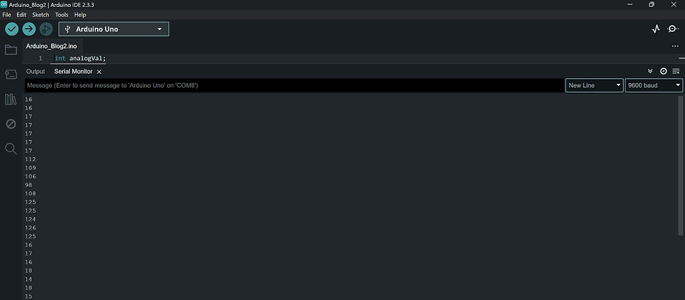
Hence, this program showcases one of the many ways we can use the Serial Monitor to observe the actions done by the Arduino board using the program that we uploaded to help verify if we have achieved the desired results.
FUN FACT TIME!!!!!

Did you know that codes like these are generally used for night lights as you can tell from the dimming and brightening of the LED in bright and dark environments respectively!!
References:
Blinking code from the e-learning package on BrightSpace
void setup() {
  pinMode(LED_BUILTIN, OUTPUT);
}

void loop() {
  digitalWrite(LED_BUILTIN, HIGH);
  delay(1000);
  digitalWrite(LED_BUILTIN, LOW);
  delay(1000);
}
Problems Encountered:
To be honest, the coding for this task was pretty simple until it came down to the breadboard 😔
There were many times when I would plug in the wrong cable to the wrong place.
For exaaaaaamplee

In the picture above, the circled wire is connected wrongly as it should be connected to the positive row instead of the negative row. This will result in the Serial Monitor not displaying the wanted values as seen in the picture below.

Correct setup:

In the picture above, the circled wire is now connected on the positive row which will enable the Serial Monitor to display the values of the LDR as seen below.

Videos of the executed program:
Task 2: Using 3 LEDS and a pushbutton
Program used:
int i;

void setup() {
  Serial.begin(9600);
  pinMode(2, INPUT_PULLUP);
  pinMode(7, OUTPUT);
  pinMode(8, OUTPUT);
  pinMode(9, OUTPUT);

}

void loop() {
  int sensorVal = digitalRead(2);
  Serial.println(sensorVal);
  if (sensorVal == LOW) {
    for (int i = 7; i <= 9; i++) {
      digitalWrite(i, HIGH);
      delay(100);
      digitalWrite(i, LOW);
      delay(100); }
  } else {
    digitalWrite(i, LOW);
  }
}
Explanation of code above:
int i;The first line of code is used to create an integer variable named "i" which can be used to store whole numbers.
Serial.begin(9600);This sentence under "void setup()", is used to establish serial communication between the Arduino board and the my computer via a USB cable. In simple terms, it also just means that I can view the activity status of the Arduino board via the serial monitor after establishing serial communication.
  pinMode(2, INPUT_PULLUP);
  pinMode(7, OUTPUT);
  pinMode(8, OUTPUT);
  pinMode(9, OUTPUT);
The first sentence sets PIN2 as a default input by enabling the internal pull-up resistor on the Arduino Board.
While the next 3 sentences declare PIN7, PIN8 and PIN9 as outputs on the Arduino board.
int sensorVal = digitalRead(2);This line of code is used to read the input of PIN2 using "digitalRead ", followed by writing and storing the input value in the integer variable "sensorVal".
In simple terms, the code is used to read and store the input of PIN2 in a repository.
Serial.println(sensorVal);This line of code is used to display the written value of "sensorVal" on the Serial Monitor when the button on the Arduino board is pressed.
if (sensorVal == LOW) {
    for (int i = 7; i <= 9; i++) {
      digitalWrite(i, HIGH);
      delay(100);
      digitalWrite(i, LOW);
      delay(100);
These lines of code run when the value of "sensorVal" is written and read as "LOW" when the button is pressed.
The second line of code is used to establish a loop that runs through the output PINs 7 to 9. This loop works by starting the output signal at PIN7 and increasing the PIN in increments of 1 until it reaches PIN9.
The last 4 sentences are used to turn ON the LED connected to PIN "i", starting with PIN7 where the LED lights up for 0.1 seconds. After which, the LED connected to PIN7 will turn OFF for 0.1 seconds before the next LED connected to PIN8 and subsequently PIN9 is turned ON.
Hence, this chunk of code works together to create the running light effect where the LED on PIN7, 8 and 9 will light up one at a time for 0.1 seconds each when the button is pressed
else {
    digitalWrite(i, LOW);
  }
This line of code runs when the button is not pressed, causing the LED connected to PIN7, 8 and 9 to remain turned OFF.
In conclusion, the program above is used to activate the running lights effect using the LED connected to PIN7 to 9 through the use of a button. This means, that when the button is pressed, the LED connected to PIN7 to 9 will turn ON and OFF one by one before repeating the sequence.
Additionally, the establishment of Serial Communication between the Arduino board and my computer has allowed us to be able to view the activity status of the program through the Serial Monitor.
ANOTHER FUN FACT!!!!!

Did you know, that just with a little bit of tweaking in the codes, programs like this can be changed to fit motion sensors to create simple reactive lighting systems which we usually see in school toilets where the lights will turn ON when someone triggers the sensor. (THATS CRAZZZZYYYY BRO)
References:
Programmable button code from the e-learning package in BrightSpace
void setup() {
  Serial.begin(9600);
  pinMode(2, INPUT_PULLUP);
  pinMode(13, OUTPUT);

}

void loop() {
  int sensorVal = digitalRead(2);
  Serial.println(sensorVal);
  if (sensorVal == HIGH) {

    digitalWrite(13, LOW);

  } else {
    for (int i=0; i < 5; i++) {
      digitalWrite(13, HIGH);
      delay(500);
      digitalWrite(13, LOW);
      delay(500);}}
}
Running light code from the Fun with Arduino package in BrightSpace
int i;

void setup() {
  pinMode(7, OUTPUT);
  pinMode(8, OUTPUT);
  pinMode(9, OUTPUT);
}

void loop() {
  for (int i = 7; i <= 9; i++) {
    digitalWrite(i, HIGH);
    delay(100);
    digitalWrite(i, LOW);
    delay(100); }
}
Problems Encountered:
After fixing the errors I made in the previous task, I thought I wouldn't make any more mistakes until I tried this task☠️
At first, after uploading the code, I realised that the light bulbs were not lighting up and there was completely nothing wrong with the set-up. So I thought the LEDS were spoilt so I swapped them out and tried again and still realised that none of the light bulbs were working.
At that point, I thought that all the LEDS I had in my group's Arduino box were spoilt and I was panicking a little bit😱

Until I took out the LED as seen from the above picture, where the shorter leg of the LED is connected to the cable connected to the designated PIN and the longer leg is connected to the resistor. I then swapped its direction and realised that I had connected the legs of the LED wrongly from the start.
OH MY LOOORRRD!!
(This was truly one of the biggest blunders of my life🤦♂️)

As seen from the picture above, in order for the LEDs to light up, the shorter leg of the LED must be connected to the resistor while the longer leg is connected to the cable connected to the designated PIN.
Videos of the executed program:
Reflection
In my opinion, Arduino Programming was honestly an activity that I found to be daunting at first as I always dreaded coding due to its complexity. However, after many trials and errors of coding and programming, it made me understand the beauty in the complicated world of coding as every code was like a note in a music piece that comes together to create a symphony.
For me, one such example of the beauty of coding was the programming of our shark prototype to have different functions during practical 2. For me, I would call this shark one of my greatest achievements in my coding journey as it not only comprises the mix of different codes that come together to perform different functions. But it's also a representation of the hard work and research that my groupmates and I had poured in to achieve our desired results.
WITHOUT FURTHER ADO, THIS IS WHAT WE ACHIEVED!! SHARK VIDEO!!!!
Throughout the trial and error phase of my Arduino journey, I managed to learn many valuable lessons and obtained many experiences with coding because of the challenges that I faced which pushed me to learn, adapt and overcome them.
Challenge 1: Understanding

For me, one such challenge was trying to understand what each code represented in the program and how the Arduino board would respond to the codes. This challenge was also coupled with the fact that there were many new terms which made my head go round and round.
This was because I had to constantly look through different sources specifically the e-learning package and the Maker UNO Edu kit module which was provided on BrightSpace. This was especially true when I was completing one of the pre-practical challenges where we had to create a programmable button that plays music when it is pressed.

After many attempts, I was still unable to program the button to work with the music program which made me feel very depressed. So, why not use ChatGPT or YouTube? It'll solve all your problems
As true as it sounded, I was still determined to overcome the challenge myself without referring to ChatGPT or YouTube for any references. So I continued to make even more attempts and through many more trials and errors, I had FINALLLLLLLLLLLLYYYYY!!! managed to make the programmable button play the music when pressed.
YYAAAAYYYYY!!!

Despite what I said, I would still like to give a special shoutout to CHATGPT!!!! as it helped me simplify the bulky and more complex codes which helped me to quicken my understanding and learning of how the code works.
Challenge 2: Logic

Another challenge I faced was trying to comprehend the logic behind how every line of code works together to run the program.

At first, I thought that once all the codes were entered into the program and an error appeared, it meant that the entire program was wrong and I ended up redoing the code multiple times.
And after those attempts, I came to realise that not every sentence of code was wrong. This meant that the code could survive and still be used as long as I changed or amended certain lines with the error.
However, this also made me realise how fragile and sensitive programs are because there were times when the program will run after it had been uploaded onto the Arduino board. However, it did not display the desired results because the codes were clashing.

This must be how Arduino felt like processing codes HAHAHAHAHAHAHAH
In other words, this meant that the Arduino board may have been receiving too much information to the point where it was unable to sort them out into smaller more manageable processes, resulting in no display of the desired results. Hence, we must be careful to not overcomplicate the processes and confuse both ourselves and the Arduino board.
Overall experience:

From all the experience I had gathered through these experiments and some personal experiments, I realised that, just like gears, programming or coding does not always have fixed answers. It involves multiple trials and many failures to understand it, and I was finally able to understand this as I found multiple ways to code and still achieve the same result. Aside from this, I also learned that coding requires a lot of patience and a very keen eye as every code needs to be accurate to the letter, otherwise, there will be an error or undesired results.
In conclusion, this programming experience partnered with Practical 2. It was truly one of the most unique experiences I had in DCHE as it allowed me to learn new technical skills such as coding and applying them to my group's shark prototype to make it more mobile. Not only that, but these experiences also targeted my soft skills such as critical thinking and troubleshooting skills which I constantly used to solve errors within my code. This helped me hone those skills I will require for my other modules such as Process Operations Skills 2 where I will be performing hands-on work in real-time. This also meant that I had to always think on the spot and attempt to make the right choices. Hence, sharpening my critical thinking and troubleshooting skills will be very useful in my chemical engineering journey and as a skill that is part of my non-work life.
Before ending this blog
THANK YOU TO ALL MY FRIENDS WHO HAVE HELPED ME WITH CODING!!!!!❤️

That's all for my second blog!!
THANKS FOR READING THIS FAR HAHAHHAHAHA
For me, this was truly one of the most brain-wrecking yet the most fun experiences I've had in DCHE due to the many ups and downs that I have faced during my experiments with programming and Arduino. Sorry that the design of the blog might look weird🙇♂️, for some reason Wix is not allowing me to place the pictures in the design I want.
I hope that my blog has been informative and helpful for everyone reading it!!
THANK YOU FOR READING!
PLEASE🙏 look forward to the next episode of my blogging series!


Comments